Norwich sits at an average elevation of about 30 metres above sea level, but that number hides sharp local contrasts. The city climbs from the Wensum floodplain at barely 5 metres to plateau edges near Mousehold Heath that top 40 metres. Every metre of that vertical change concentrates lateral earth pressure behind a retaining structure. For a retaining wall design in Norwich, the starting point is rarely the wall itself: it is what the ground will do across two seasons of wetting and drying in a maritime climate. The Upper Chalk beneath the city is competent but fissured, the overlying sands and gravels drain freely until they don't, and the river terrace deposits shift between granular and cohesive behaviour over a few hundred metres. A desk study that ignores the British Geological Survey sheet for Norwich (Sheet 161) is already behind. We combine that mapping with site-specific borehole data to define the earth pressure envelope before a single section is drawn.
A retaining wall in Norwich is a groundwater management device as much as a structural element. Design the drainage first, then size the stem.
Methodology applied in Norwich
Local geotechnical conditions in Norwich
Norwich has been building on slopes since the Anglo-Saxon settlement at Westwic. Medieval chalk mines tunnel under parts of the city centre, and Victorian terraces were cut into valley sides without engineered retaining works. Today, when a developer excavates for a basement on Newmarket Road or Thorpe St Andrew, the retained cut may intersect old backfilled pits or undocumented wells. The geotechnical risk is not the chalk failing in compression; it is a localised collapse into a void that removes passive support from the wall toe. We run a ground-penetrating radar survey as a matter of course on any Norwich site within 200 metres of mapped chalk workings. The second risk is long-term softening: Norwich Chalk exposed in an excavation face can lose 40% of its undrained shear strength over five wet-dry cycles, a phenomenon well documented in CIRIA C574. A wall designed on peak strength from a dry borehole sample will gradually shed factor of safety unless the face is sealed immediately after excavation.
Our services
The retaining wall design process starts with a ground investigation and moves through staged analysis to construction-ready drawings. Every Norwich project includes a drainage specification because the wall's long-term performance depends on it.
Gravity and Cantilever Wall Design
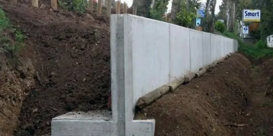
For retained heights up to 4 metres in Norwich's river terrace gravels, a reinforced concrete cantilever wall is often the most economical section. We design the stem, base, and shear key in a single iterative loop, checking bearing capacity on the chalk or dense sand founding stratum. For heights below 1.5 metres, a mass concrete gravity wall with a 1:4 battered face can be detailed with minimal reinforcement, provided the backfill is free-draining and a 100 mm perforated drain runs at the heel. All designs include a construction sequence specifying temporary batter slopes and any need for trench support during excavation.
Embedded Retaining Walls and Basement Retention
When the excavation goes deeper than 4 metres, or when adjacent structures limit the excavation footprint, we switch to an embedded wall solution. In Norwich chalk, a contiguous bored pile wall with 600 mm diameter piles at 750 mm centres typically provides adequate groundwater cut-off if the piles socket 1.5 metres into competent Grade I/II chalk. We model the wall in a soil-structure interaction analysis using spring stiffnesses calibrated to the site-specific modulus from pressuremeter testing, not generic chalk values. The output is a bending moment and shear force envelope used by the structural engineer to detail the reinforcement cage.
Questions and answers
What does a retaining wall design package cost for a typical Norwich residential project?
For a single retaining wall on a residential site in Norwich, the design package ranges from £850 to £2,940. A simple gravity wall under 1 metre retained height sits at the lower end. A reinforced cantilever wall with drainage design, structural calculations, and construction drawings for a 2.5-metre retained height typically falls between £1,500 and £2,200. The upper end covers embedded wall solutions or basement retention with soil-structure interaction modelling. Each quote is project-specific and includes the desk study review of BGS mapping and any historical chalk workings records for the site.
Do you need a ground investigation before designing a retaining wall in Norwich?
Yes, without exception. A retaining wall design under Eurocode 7 requires characteristic values for the soil's effective friction angle, cohesion, and unit weight. In Norwich, the ground can change from chalk to sand to alluvial clay within 50 metres, so borehole data is essential. We typically specify two window sampler boreholes for a residential wall, one at the wall location and one 5 metres behind it, both extending to twice the retained height below founding level. Laboratory testing includes classification, triaxial compression on undisturbed samples, and pH/sulphate testing for concrete specification.
What drainage provisions are required behind a retaining wall in Norwich?
Drainage is mandatory. BS 8002:2015 requires a drained design unless the wall is specifically designed as a water-retaining structure. For a typical Norwich wall, we specify a 300 mm minimum thickness of free-draining granular backfill (6G or 6I material per Series 600) directly behind the stem, a perforated collector pipe at the base graded to a positive outfall, and a geotextile filter wrapping the granular column to prevent fines migration from the retained soil. On chalk sites, we also include a blinding layer at the excavation base to prevent softening of the chalk surface before the footing is cast. More info.