A common mistake on Norwich construction sites is treating the entire city as if it sits on a single, predictable stratum. The reality, particularly when you move east of the city centre toward the River Yare, is a complex sequence of soft alluvial clays, peat lenses, and silty sands that can compress unevenly under load. We have seen projects near the Broadland Business Park where shallow footings specified without ground improvement led to differential settlements exceeding 40 mm within the first year. Stone column design becomes the primary risk-management tool in these conditions, transforming the mass behaviour of the soft deposit through a network of compacted granular inclusions. Our approach integrates site-specific data from the CPT test to calibrate the column stiffness and spacing, ensuring the reinforced ground meets the serviceability limit states defined in BS EN 1997-1:2004.
In Norwich alluvium, a well-designed stone column network can reduce total settlement by 50-65% compared to untreated ground, turning a marginal site into a buildable one.
Methodology applied in Norwich
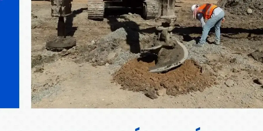
Local geotechnical conditions in Norwich
The ground profile in Thorpe Hamlet, close to the River Wensum, presents one set of risks, while the higher terraces around Eaton offer another. Down by the river, the presence of saturated organic silts introduces a time-dependent settlement component that a purely elastic design model will miss. We have observed post-construction settlements in untreated zones that continue for over eighteen months, driven by primary consolidation of low-permeability silts. Up on the Cringleford chalky till, the risk shifts to the interface between the stiff upper layer and any deeper softened chalk—stone columns here must be designed to avoid punching failure through the crust. Across all Norwich postcodes, the most underestimated risk is the sensitivity of the local soft clays to remoulding during column installation. Using the wet top-feed method without proper casing in sensitive soils can generate excess pore pressures that temporarily reduce the undrained shear strength by 30-40%, delaying the gain in column stiffness. We specify installation sequence and pore pressure dissipation checks as part of the design package to mitigate this.
Our services
Our stone column design service in Norwich encompasses the full analytical and reporting chain required to validate a ground improvement strategy. We work directly with specialist contractors to ensure the installation methodology aligns with the design assumptions.
Composite Ground Modelling
Finite element and unit cell analyses using Plaxis 2D to quantify settlement reduction and bearing capacity improvement for strip and raft foundations on the Wensum and Yare floodplains.
Installation Method Specification
Detailed recommendations for dry bottom-feed versus wet top-feed techniques based on the sensitivity of the Norwich alluvium, including casing requirements and pore pressure monitoring triggers.
Performance Verification Testing
Design and supervision of post-installation plate load tests and zone load tests in accordance with the ICE Specification for Ground Treatment, correlated with the original CPTu baseline.
Questions and answers
What is the typical cost range for a stone column design package for a residential development in Norwich?
For a residential project in Norwich, the design package typically falls between £1,010 and £4,100, depending on the number of blocks, the complexity of the alluvium profile, and the level of numerical modelling required. A straightforward site with a uniform soft clay layer and a single foundation type will be at the lower end, while a mixed-use scheme with varying column grids and a requirement for coupled consolidation analysis sits at the upper end.
How do you determine the stone column length when the alluvium contains peat layers?
Column length is dictated by the depth to a competent bearing stratum, which in Norwich is typically the glacial till or the Crag Group sands. When peat is present, we never allow column toe-out within the organic layer. The design must specify full penetration through the peat and at least 0.5 m of socket into the underlying stiff material to prevent a bearing capacity failure. We confirm this depth using CPTu profiles, as peat has a distinct cone resistance signature (qt < 0.5 MPa) that is unmistakable in the Yare Valley.
Can stone columns be designed beneath a piled raft system in Norwich?
Yes, we frequently design stone columns to support a granular load transfer platform beneath piled rafts in the city centre, particularly where demolition of historic structures has left variable fill over alluvium. The columns reduce the lateral loading on the piles from consolidating soft soil and improve the platform stiffness. The design must account for the interaction between the column heads, the platform, and the piles—a coupled analysis we perform using Plaxis 3D when the pile grid is irregular.
What are the key BS EN 1997 limit states you check in a Norwich stone column design?
We verify both ultimate and serviceability limit states. For ULS, the check is against column bulging failure in the softest layer—using the Hughes and Withers (1974) cavity expansion method—and against group bearing failure at the toe. For SLS, the primary check is total and differential settlement of the reinforced ground, modelled via the Priebe (1995) method or FEM. In Norwich, where angular distortion tolerances for masonry-clad buildings are tight, the SLS check often governs the required area replacement ratio.